Panel sector antenna FA-20 (18-22 dBi)
I would like to present to you a description of the design of the FA-20 panel sector antenna, which, despite its simplicity, has proven itself to be highly productive and reliable.
1. Introduction
The original description of the author is located at http://sterr.narod.ru/wifi/fa20.htm. Description from Volodya - http://vbm.lan23.ru/wifi/fa20.html. You can find a lot of positive reviews about this design on the Internet, but it is noted that manufacturing accuracy is very important, especially for vibrators and mounting holes in the reflector. Maintaining the distance between the reflector and the vibrators is also of great importance. Be sure to adhere to the specified dimensions, this will allow you to achieve maximum antenna efficiency.
2. Design
The antenna consists of four structural elements: a reflector (1), two types of vibrators (2, 3) and a connecting bus (4), which serves to connect the vibrators:

Reflector

Vibrators
The author of the original description, Sterr, recommends using food-grade tin as a material for vibrators; VBM made these elements from double-sided foil PCB.
3. Materials
To assemble the antenna we will need:
- Single-sided foil PCB (for reflector)
- Double-sided foil PCB (for vibrators)
- Strip of brass or copper foil (for busbar)
- Aluminum corner 25×25 mm
- Rivets
- F connector
4. Manufacturing
First of all, you need to make a reflector “trough”. To do this, according to the drawing, we cut out a rectangle from foil PCB 490×222 mm for the bottom, mark it (it is best to core from the foil side) and drill holes with a diameter of 2.5 mm for the stands for vibrators, tin them. After this, we make sides of the appropriate size from an aluminum corner 25x25 mm, and fasten them with rivets on the back side of the reflector:

Blanks

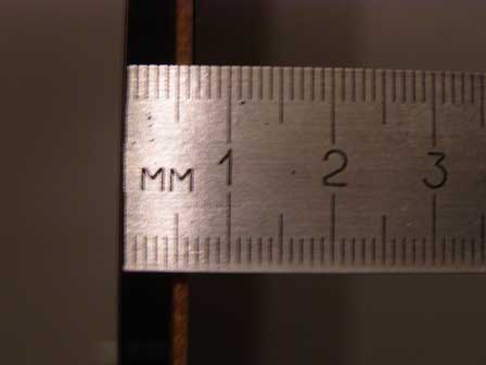
For accurate markings, it is best to use a caliper

When attaching the corners with rivets, also secure the edges of the corners
After assembling the “trough” of the reflector, it can be strengthened a little by gluing the corners on the back side mounting tape, and glue the vertical seams with two-component epoxy glue:

Strengthening the structure
Volodya came up with an original technology for making vibrators from fiberglass, foil-coated on both sides. Advantage this method the fact that from one workpiece two absolutely identical vibrators are obtained.
First, a rectangular blank of the required dimensions is cut out from textolite:

Blank for making vibrators
- Cut rectangles with metal scissors 1
- We stratify the fiberglass, we try to stratify halves of the same thickness
- We make slits along the red lines of the rectangles with 2 ordinary household scissors
- Take a broken hacksaw blade for metal and cut 2 rectangles along the green lines
- Using fine sandpaper, carefully clean the ends of the resulting vibrators

Ready-made vibrators
As a result, we get two vibrators of identical sizes. Care must be taken to ensure that the non-foil side of the vibrator is smooth; this may require removing a layer of fiberglass. After this, we drill and tin tin holes with a diameter of 2.5 mm for the posts.
After making the vibrators, it is necessary to make a bus (4) from brass or copper foil, with which we will later connect the “tails” of the vibrators.
All elements of the future antenna are ready, you can begin assembly. To do this, you need to find a spacer for the vibrator. Select its thickness so that the total thickness of the PCB and gasket gives a distance of 6 mm between the reflector and the vibrator foil.
To install vibrators, it is best to use smooth, thick copper wire with a diameter of about 2 mm. We cut it into small pieces and solder them in the “trough” holes. Then, placing a spacer next to the stand, we solder one edge of the vibrator, then the other in the same way, having previously moved the spacer. We bite off the excess parts of the racks. When installing, narrow vibrators are placed at the edges, wider ones in the center.

Antenna assembly
After installing the vibrators, we fix the connector on the “trough” and connect the “tails” of the vibrators using a busbar, carefully soldering them, then solder the central core of the connector to the busbar.
5. Installation
The easiest way to attach the antenna to a block is by drilling holes in the “trough” between the central vibrators and fastening it with screws or screws. If you plan to mount the antenna on a pipe, it is better to rivet an aluminum corner about 30 cm long to the antenna on the back side of the reflector, then attach the corner to the mast using clamps or ties.
WI-FI antenna FA-20 (FA-20) we make the most powerful directional panel antenna ourselves!
This article describes how you can make your own powerful FA-20 panel antenna with vibrators made by etching on foil PCB.
The manufacturing technology of the FA-20 is similar to the panel antenna we made earlier. When building this antenna, you can safely follow this article, the only difference is that this antenna is DC closed.
Important! The more carefully the WI-FI antenna is assembled, the more efficiently it will work.
What you will need for this:
A piece of foil PCB 430x200 mm, thickness 1.5 mm;
- bolts - O 3 mm and nuts for them (8 bolts for the vibrators + 3 nuts per bolt, 4 bolts for fastening the connector. Total: 12 bolts, 32 nuts);
- a piece of tin 435x205 mm (for the reflector);
- a set of RF connectors 50 Ohm (N type male-female set for antenna, connector for access point);
- 50 Ohm cable (RG-8X);
- ferric chloride for etching boards;
- a can of paint (for painting tin) and non-conductive varnish for textolite;
- antenna stencil on vinyl self-adhesive film and mounting film for transferring the antenna to textolite.
I ordered the antenna stencil from a company that specializes in plotter cutting, and as many as 4 antenna patterns fit onto a piece of vinyl, the price did not change because of this, and all this together with cutting and mounting film cost a very modest amount.
By the way, here is the stencil itself [FA-20], ready for cutting.
The remaining items, except for the spray paint, were obtained on the radio market.
Antenna stencil on PCB.
After this, you can proceed directly to the manufacture of the antenna. First, we clean and degrease the foil surface of the PCB with acetone or solvent. Then we cut off one stencil from the common piece and glue the mounting film on top of it. It is most convenient to stick vinyl onto PCB and remove the mounting film at an angle of 45° (The piece of PCB I bought was slightly larger, but nothing prevents me from cutting it off later?). The stencil is carefully rubbed into the textolite.
Then you need to find a container in which the antenna will be etched. (I couldn't find a container that size, so I used a lid from an old Soviet TV into which I placed the plastic film, I already poured warm water into it and poured in ferric chloride).

Reflector blank and vibrators on PCB.
So, the textolite is etched, the next stage is marking and drilling. First, we mark the drilling points on the vibrators, this is their center (for a narrow vibrator, the horizontal center is 21.5 mm, vertically 27 mm, for a wide vibrator it is 24 mm horizontally and 27 mm, respectively). The connection point with the central contact of the connector relative to the center of the right vibrator is 60.5 mm (or 60.7 mm from the edge of the narrow part of the vibrator on the right). To put it simply, we are looking for the center of the wide part of the vibrator. Kernim! Then we align the workpiece with etched vibrators in the center of the tin plate and fix it (for example, with a clamp) and drill holes.
Now you need to screw the connector and paint the tin plate, not forgetting to protect the connector from getting paint on it. While the paint is drying, you can screw the bolts into the vibrators and tighten them from the back side (!) with two nuts. Why two? Let's look: the PCB thickness is 1.5 mm, two nuts are 4.5 mm. In total, the required distance from the reflector to the vibrator was obtained.

The gap between the reflector and the vibrators must be strictly observed!
Although there is another option, use brass screws with which the motherboard is screwed to the case system unit, their height is 6 mm. This option is suitable for cases where the vibrator is made of tin, brass or other sheet metals.
The gap between the reflector and vibrators.
When the paint has dried, you can begin assembling the antenna, twist the PCB to the base, solder the central core of the connector, varnish the vibrators on the PCB, and assemble the cord.

FA-20 antenna assembly, pigtail, wall mount with clamps.

Antenna FA-20. Rear view.
That's all! The antenna is ready to go!
Good luck!
The Internet today is as necessary as air, and modern life without it is simply unthinkable. And how joyful it is to realize that there are more and more free access points using Wi-Fi technology. But not everyone manages to use them, because the signal is not strong enough. In such a situation, the FA-20 panel antenna will help out, which today we will suggest you make with your own hands.
In fact, this device is quite simple and will not cause any difficulties in manufacturing even in an ordinary apartment. But the benefits from it will be quite noticeable, and maybe even some radio amateurs will be encouraged to start manufacturing such equipment seriously.
Antenna characteristics
The panel antenna consists of 2 main parts - a reflector and vibrators. The line of vibrators is connected by a common contact, from which the coaxial cable leading to the nest external antenna Wi FI router attached to the back of the device. The antenna works as an amplifier, which can be judged by comparing the signal power from the standard antenna of the router (the author used tp-link TL-WN722N) - 5db, and from the FA-20 - 22db.Required materials:
- Foil textolite one-sided or getinaks, 430x200 mm, thickness - 1.5 mm;
- A piece of sheet metal (best galvanized), 435x205 mm, thickness 0.5-1 mm;
- TV coaxial cable RG-8X 50 Ohm;
- Drawing template of antenna vibrators printed on vinyl film;
- Photoresist;
- Ferric chloride for etching boards;
- A can of aerosol varnish for textolite;
- Soda, acetone or alcohol;
- Hardware: 3 mm bolts – 12 pcs., nuts – 32 pcs.


Tools:
- A drill with a cutting disc for cutting getinax;
- Drill with drill 3-3.5 mm;
- Soldering iron with solder;
- Painting knife, scissors;
- Pliers, metal scissors;
- Construction rubber roller for rolling films;
- Bath for etching the antenna board;
- A piece of glass and an ultraviolet lamp for photolithography;
- Hairdryer or iron to warm up the photoresist;
- Sandpaper-zero;
- Hot glue gun;
- Core, hammer;
- Metal ruler for marking holes.
Making a Wi-Fi antenna
Stage one - making a panel of vibrators
We mark a sheet of foil PCB to the size of our antenna, and cut it out with a cutting disc of a drill. This procedure can also be performed with a regular paint knife, making cuts along the marking line on both sides of the sheet, and then breaking them off by hand.


On transparent film for inkjet printers print out a template for the antenna vibrators. It will come out of two sheets, which are then easily connected to each other.


To etch using photoresist technology, it is necessary to prepare the foil side of the getinax by cleaning it with a zero. You can degrease surfaces using acetone or alcohol.


We place the photoresist film on the getinax, cutting it to size with scissors. We remove the protective layer and glue the photoresist, getting rid of air bubbles by rolling with a rubber wallpaper roller.


After this, we apply the vibrator template film and cover it with ordinary glass. We use an ultraviolet lamp to illuminate the photoresist. Holding time different manufacturers this material is different. The author needed 5 seconds for his film, ordered from China. for each processed area of the board.


Now it is necessary to additionally heat the photoresist so that it firmly adheres to the surface of the getinax. We remove the template, a sheet of glass, and heat the film with a hairdryer or iron through the paper. Remove the top protective layer of photoresist.


We wash off the unexposed photoresist in a baking soda solution, placing the getinax plate in the bath. After a few minutes, remove any remaining film with a used toothbrush.


Getinax is ready for pickling. We dilute ferric chloride in warm water and dip the plate into a container with the solution. It must be stirred periodically.


We saturate the old lye solution with soda ash and place the plate in it to get rid of the remaining photoresist. We wash the resulting board with plain water.


We mark the centers of the rectangles of the vibrators on the board, and use a core to drill them. The hole must be made for the mounting bolts 3 mm. The author used a step or precision conical drill, which is convenient for removing burrs.


Stage two - preparing the reflector
From a piece of galvanized sheet metal, which is the most resistant to corrosion, we cut out a copy of our vibrator plate. The holes for fastening the bolts can be easily transferred to the sheet metal by making notches with the same drill. We drill holes on the tin through a wooden lining.


We tighten the bolts with two nuts on the back side of the plate, making the required gap between the reflector 3 mm, and the total distance between the vibrators and the reflector 6 mm. We secure the tin using the third nut.

The Internet today is as necessary as air, and modern life without it is simply unthinkable. And how joyful it is to realize that there are more and more free access points using Wi-Fi technology. But not everyone manages to use them, because the signal is not strong enough. In such a situation, the FA-20 panel antenna will help out, which today we will suggest you make with your own hands.
In fact, this device is quite simple and will not cause any difficulties in manufacturing even in an ordinary apartment. But the benefits from it will be quite noticeable, and maybe even some radio amateurs will be encouraged to start manufacturing such equipment seriously.
Antenna characteristics
The panel antenna consists of 2 main parts - a reflector and vibrators. The line of vibrators is connected by a common contact, from which a coaxial cable is led out, leading to the jack of the external antenna of the Wi FI router, mounted on the back of the device. The antenna works as an amplifier, which can be judged by comparing the signal power from the standard antenna of the router (the author used tp-link TL-WN722N) - 5db, and from FA-20 - 22db.
Required materials:
- Foil textolite one-sided or getinaks, 430x200 mm, thickness - 1.5 mm;
- A piece of sheet metal (best galvanized), 435x205 mm, thickness 0.5-1 mm;
- TV coaxial cable RG-8X 50 Ohm;
- Drawing template of antenna vibrators printed on vinyl film;
- Photoresist;
- Ferric chloride for etching boards;
- A can of aerosol varnish for textolite;
- Soda, acetone or alcohol;
- Hardware: 3 mm bolts – 12 pcs., nuts – 32 pcs.


Tools:
- A drill with a cutting disc for cutting getinax;
- Drill with drill 3-3.5 mm;
- Soldering iron with solder;
- Painting knife, scissors;
- Pliers, metal scissors;
- Construction rubber roller for rolling films;
- Bath for etching the antenna board;
- A piece of glass and an ultraviolet lamp for photolithography;
- Hairdryer or iron to warm up the photoresist;
- Sandpaper-zero;
- Hot glue gun;
- Core, hammer;
- Metal ruler for marking holes.
Making a Wi-Fi antenna
Stage one - making a panel of vibrators
We mark a sheet of foil PCB to the size of our antenna, and cut it out with a cutting disc of a drill. This procedure can also be performed with a regular paint knife, making cuts along the marking line on both sides of the sheet, and then breaking them off by hand. 


We print a template of the antenna vibrators on transparent film for inkjet printers. It will come out of two sheets, which are then easily connected to each other. 


To etch using photoresist technology, it is necessary to prepare the foil side of the getinax by cleaning it with a zero. You can degrease surfaces using acetone or alcohol. 


We place the photoresist film on the getinax, cutting it to size with scissors. We remove the protective layer and glue the photoresist, getting rid of air bubbles by rolling with a rubber wallpaper roller. 


After this, we apply the vibrator template film and cover it with ordinary glass. We use an ultraviolet lamp to illuminate the photoresist. The holding time for different manufacturers of this material differs. The author needed 5 seconds for his film, ordered from China. for each processed area of the board. 


Now it is necessary to additionally heat the photoresist so that it firmly adheres to the surface of the getinax. We remove the template, a sheet of glass, and heat the film with a hairdryer or iron through the paper. Remove the top protective layer of photoresist. 


We wash off the unexposed photoresist in a baking soda solution, placing the getinax plate in the bath. After a few minutes, remove any remaining film with a used toothbrush. 


Getinax is ready for pickling. We dilute ferric chloride in warm water and dip the plate into a container with the solution. It must be stirred periodically. 


We saturate the old lye solution with soda ash and place the plate in it to get rid of the remaining photoresist. We wash the resulting board with plain water. 


We mark the centers of the rectangles of the vibrators on the board, and use a core to drill them. The hole must be made for the mounting bolts 3 mm. The author used a step or precision conical drill, which is convenient for removing burrs. 


Stage two - preparing the reflector
From a piece of galvanized sheet metal, which is the most resistant to corrosion, we cut out a copy of our vibrator plate. The holes for fastening the bolts can be easily transferred to the sheet metal by making notches with the same drill. We drill holes on the tin through a wooden lining. 


We tighten the bolts with two nuts on the back side of the plate, making the required gap between the reflector 3 mm, and the total distance between the vibrators and the reflector 6 mm. We secure the tin using the third nut. 


In the upper part of the reflector we make a hole for a coaxial cable, the central core of which must be soldered to the vibrator plate, and the braid to the reflector.
We solder the second end of the cable in place of the external antenna to the router. We attach it to the reflector from the back of the antenna using hot glue. 


We protect the front side of the vibrator board from oxidation with aerosol colorless varnish. 


For home use This antenna can be placed on a windowsill or balcony. If you plan to use it outdoors, any bracket leading to a mast on the roof or outside the window can easily be attached to the reflector. 


Watch the video
You may like:
- Drawings on windows for the New Year 2018 with toothpaste,…
- From all this, the girl created incredible beauty...
This article is based on personal experience construction WiFi networks over a long distance. In our case, the goal was set to get out of the house unlimited internet to work. After reading various sources and a bunch of forums, the decision was made to build this link and with full confidence we set to work. I will also say that a distance of 5 km, by the standards of forum members, is not a long distance, but at most an average one.
In our case, the “pioneer” one was taken as a basis. WiFi hotspot access from the manufacturer D-link - DWL 2100AP. On our website you can get advice, and in the Download section you can find useful programs for this point. The decision was made for a long time and painfully - which antenna to choose, and finally, thanks to the forum members, the choice fell on a successful model of the 2.4 GHz antenna - FA20. Easy to manufacture and efficient in operation, it “forgave” us some flaws in its production.
What we needed:
After selecting the antenna, we thought about the method of its manufacture. It was customary to make a WiFi antenna from PCB, but using our own technology. Somewhere in the forums they talked about a method for splitting double-sided PCB, about cutting it out of foil, but we decided to go our own way, and I hope that our experience will be useful to someone. The antenna pattern can be downloaded here -.
The vibrators were cut out using a jigsaw, and slits were made in pre-marked places with a utility knife.


Using a knife and tweezers, carefully remove the copper layer from the PCB. Cut out the reflector and sides. Tip: take into account the thickness of the cut line when marking the PCB, and also do not forget to process the edges of the PCB with a fine file. Two copper strips were cut from a 1mm thick copper plate.


Copper wire was used to connect the vibrators to the reflector. To maintain a distance of 6 mm, it is necessary to find or make a gasket with a thickness of 4.5 mm, taking into account the textolite. In the segment copper tube(antenna of any radio), the stripped RG-6U cable is inserted tightly. We insert our tube with cable from the reverse side into a pre-drilled hole in the reflector and solder it to the copper layer of the reflector, and the central core of the cable to the copper strip. Since the standard antenna is no longer useful to us, we use it to make a connector for the second end of the cable.


We took the mounting of the antenna to the mast seriously. We needed to easily rotate the antenna in any plane, this is necessary for precise tuning. It was decided to mount the antenna on a ball from a car, which in turn is mounted on a mast made of an iron angle 2 m high. An example of attaching a ball to an antenna in the photo.