I have an elderly CRT (CRT) SONY 200 GS Trinitron monitor. Great colors good condition, but already morally outdated, although physically still at least somewhere. The idea of using this ordinary computer monitor with a 15 pin VGA (D-sub) input as a TV has been around for a long time, but it never came to fruition. And now this long time has come this moment.
A converter model HDV200-A was ordered. It allows you to transform the usual standard signal Video from any source: DVD, VCR, TV tuner (DVB-T, DVB-C, DVB-S), cameras, etc. in VGA (D-sub), which is standard in almost all monitors.  The converter supports the following output resolutions: 800X600@60Hz, 800X600@75Hz, 1024X768@60Hz, 1280X1024@60Hz, 1440X900@60Hz, 1680X1050@60Hz, 1920X1080@60Hz, 1920X1200@60Hz .
Supports (auto-detect) the following color formats: PAL, NSTC and SECAM. It was the presence of SECAM that turned out to be decisive when choosing this particular model, because it was supposed to be used to convert a signal from a DVB-T digital terrestrial tuner, where SECAM could possibly be used.
The order from the Middle Kingdom was sent on December 5, on January 17 it arrived Postal office. I received it in my hands on January 22 and checked it immediately.
The kit includes a cardboard box, the converter itself, a power supply (it’s bad that it has flat power contacts, but I knew about it and therefore bought an adapter for round ones in advance), two cords - RCA to Video and S-VIDEO, a small manual. The cardboard box was wrapped in two layers of thin polyethylene foam sheet and everything was packaged in a black bag. There is no damage during shipment. 
The Video signal was taken from the Vityaz HDR-826 HD digital tuner
This tuner is universal and allows you to receive digital signals, both terrestrial - DVB-T, and cable - DVB-C, it is possible to connect an access card (encoded channels). Outputs (tuner) - SCART, RCA, HDMI. In our case, we used the SD signal (576i) of the DVB-C digital package of the local cable operator. Photo from the monitor screen of the Kino Hit channel below  Current resolution is 1280X1024@60Hz. The image is clear, without tails, repetitions, transitions and any kind of taffy, because... Initially the signal from the digital tuner is used.
Resolution is set by successively pressing the Resolution button. Another Menu button changes the monitor parameters - Brightness, Saturation, Contrast, Hue.
Input button – switches between input signals from different sources.
When selected, the current modes are displayed on the monitor screen and disappear after a few seconds. The current settings appear to be saved when the converter's power is turned off. On the side of the converter there is a connector for connecting an external 5V power supply. Next to it is a power indicator – a red LED covered with a quality control sticker. It looks pretty cool, i.e. illuminated sticker. 
During operation, the converter body heats up to approximately 45 degrees.
Let me make a reservation right away: only an SD signal was used - 576i, (more precisely 625 lines), was not tested with an HD signal 1920X1080, although the converter and tuner support this mode, but the local cable operator only plans to broadcast in HD, and besides, a modern monitor is needed with a diagonal of at least approximately 22" or more. And most likely it will be an SD signal. This issue requires further study
Sound (Audio), of course, from the tuner is sent to any stereo amplifier (for example, the same computer speakers).
I am very pleased with the purchase, I finally found a use for my old monitor. Now you can think about buying the Iiama Prolite XB2483HSU.
It is indeed a very useful and necessary thing.
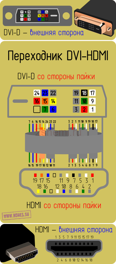
The name HDMI (High Definition Multimedia Interface) literally translates as High Definition Multimedia Interface. A standard HDMI cable consists of 19 wires. Knowing the cable pinout diagram, you can connect an HDMI socket to it or repair a broken wire or replace a damaged connector. The individual socket contacts are numbered from right to left, with odd-numbered contacts in the top row and even-numbered contacts in the bottom row.
HDMI is used as an interface for transmitting high quality uncompressed digital video and audio signals. HDMI interface supports maximum resolution transmission of video and audio signals in formats such as DTS, LPCM, DVD-Audio, Dolby Digital, Super Audio CD, etc. HDMI can have a maximum data rate of up to 10.2 Gbps (340 MHz). The interface uses the TMDS protocol.

HDMI connectors (mini, micro) and their pinouts
- Type "A" - 19 pins, specification 1.0
- Type "B" - 29 pins, specification 1.0
- Type "C" - 19 pins (mini), specification 1.3
- Type "D" - 19 contacts (micro), specification 1.4
- Type "E" - 19 pins, specification 1.4

Pinout HDMI Type A (19pin)

Pinout HDMI Type B (29pin)

Pinout HDMI Type C mini (19pin)

Pinout HDMI Type D micro (19pin)
| Contact | Descriptionsignal | |||
| HDMI Type A (standard) |
HDMI Type B |
HDMI Type C (mini) |
HDMI Type D (micro) |
|
| 1 | 1 | 2 | 3 | TMDS Data2+ (Video signal, pair 2) |
| 2 | 2 | 1 | 4 | TMDS Data2 Shield |
| 3 | 3 | 3 | 5 | TMDS Data2- (Video signal, pair 2) |
| 4 | 4 | 5 | 6 | TMDS Data1+ (Video signal, pair 1) |
| 5 | 5 | 4 | 7 | TMDS Data1 Shield |
| 6 | 6 | 6 | 8 | TMDS Data1- (Video signal, pair 1) |
| 7 | 7 | 8 | 9 | TMDS Data0+ (Video signal, pair 0) |
| 8 | 8 | 7 | 10 | TMDS Data0 Shield (Video Signal Shield) |
| 9 | 9 | 9 | 11 | TMDS Data0- (Video signal, pair 0) |
| 10 | 10 | 11 | 12 | TMDS Clock+ ( Clock frequency video signal) |
| 11 | 11 | 10 | 13 | TMDS Clock Shield |
| 12 | 12 | 12 | 14 | TMDS Clock- (Video clock frequency) |
| — | 13 | — | — | TMDS Data5+ (Video signal, pair 5) |
| — | 14 | — | — | TMDS Data5 Shield (Video Signal Shield) |
| — | 15 | — | — | TMDS Data5- (Video signal, pair 5) |
| — | 16 | — | — | TMDS Data4+ (Video signal, pair 4) |
| — | 17 | — | — | TMDS Data4 Shield (Video Signal Shield) |
| — | 18 | — | — | TMDS Data4- (Video signal, pair 4) |
| — | 19 | — | — | TMDS Data3+ (Video signal, pair 3) |
| — | 20 | — | — | TMDS Data3 Shield (Video Signal Shield) |
| — | 21 | — | — | TMDS Data3-(Video signal, pair 3) |
| 13 | 22 | 14 | 15 | CEC (Signal) |
| 14 | 23 | 17 | 2 | Reserved (HDMI 1.0-1.3c) HEC Data- (HDMI 1.4+ with Ethernet) |
| — | 24 | — | — | Reserved (Reserved in the cable, but not connected) |
| 15 | 25 | 15 | 17 | SCL (I2C Serial Clock for DDC) |
| 16 | 26 | 16 | 18 | SDA (I2C Serial Data for DDC) |
| 17 | 27 | 13 | 16 | DDC/CEC/HEC Ground |
| 18 | 28 | 18 | 19 | +5V Power (max 50 mA) |
| 19 | 29 | 19 | 1 | Hot Plug Detect (All versions) HEC Data+ (HDMI 1.4+ with Ethernet) |

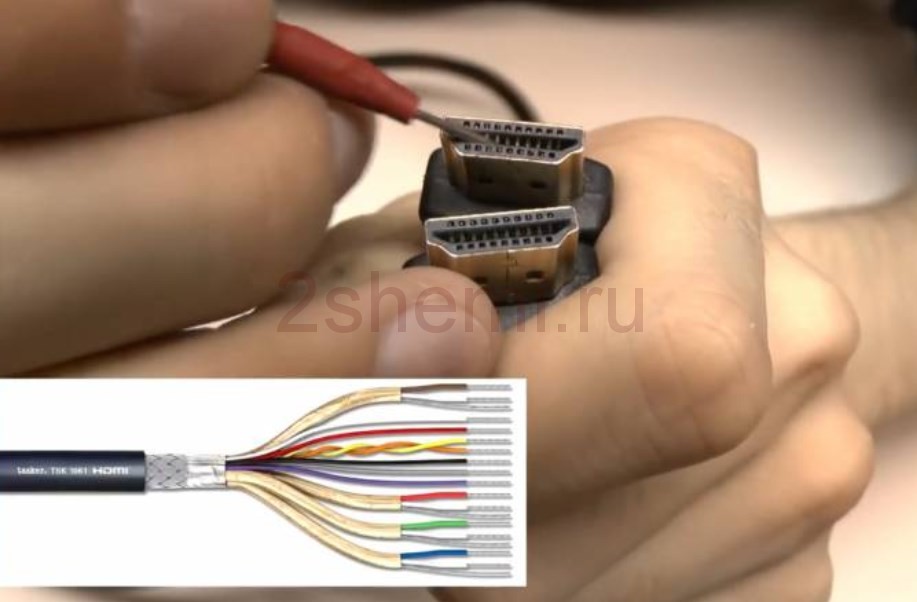
HDMI cable pinout by color
The HDMI cable is divided into 5 groups of 3 cores. And 4 more wires go separately. The connector provides switching of four groups of shielded symmetrical circuits for transmitting digital video signals (aluminum foil shield), separate wires for service data and power.

| Contact number | Purpose | Wire color | Note |
| 1 | Video signal 2+ | White | Red group |
| 2 | Video signal 2 screen | Screen | |
| 3 | Video signal 2- | Red | |
| 4 | Video signal 1+ | White | Green group |
| 5 | Video signal 1 screen | Screen | |
| 6 | Video signal 1- | Green | |
| 7 | Video signal 0+ | White | Blue group |
| 8 | Video signal 0 screen | Screen | |
| 9 | Video signal 0- | Blue | |
| 10 | Tact + | White | |
| 11 | Tact screen | Screen | |
| 12 | Tact - | Brown | |
| 13 | CEC Signal | White | |
| 14 | Utility | White | Yellow group |
| 15 | Asymmetric bus signal SCL | Orange | |
| 16 | Asymmetric bus SDA signal | Yellow | |
| 17 | Earth | Screen | Yellow group |
| 18 | Power supply +5 V | Red | |
| 19 | Connection detector | Yellow | Yellow group |
There is no single color marking for cores and each cable manufacturer may have its own marking. In a test copy HDMI cable This is exactly what was used.

HDMI cable pinout for sound
Sound on modern TVs or set-top boxes sometimes comes out only via HDMI (without regular audio outputs or like on headphones, that is, there is no old audio output). Therefore, you have to think about how to “extract” sound signal from the eychdimiai nest. To do this, you can buy a special audio adapter on Ali (600 rubles) in the form of a small box that extracts sound from the signal coming via HDMI and outputs it in analog form to two RCA tulip connectors or in digital form to optical SPDIF.
HDMI-DVI pinout
Pinout of HDMI connector to RCA tulip
Typically, an HDMI to RCA adapter is used when it is necessary to reproduce or transmit data in video and audio format. This connecting cable has a built-in special chip that acts as a converter digital signal HDMI to composite video or audio. This signal is then sent through the tulip connector to the TV screen.

To convert a purely digital HDMI signal into an analogue one (S-Video, component or composite), you need not just an adapter, but a whole device consisting of a digital signal receiver, several DACs, a television signal conditioner, and a bunch of other little details. It's too complicated to just call it an adapter.
The design of the adapter is made in the form of a miniature hardware module with wire. At one end there is an HDMI connector, and at the other there are three multi-colored tulip connectors.
HDMI-VGA adapter pinout

The HDMI-VGA adapter consists of more than just wires and connectors. An HDMI-VGA cable is a whole circuit on a chip, which is very difficult to solder yourself - just buy a ready-made adapter (as is the case with extracting sound from such a cable). Its price on Ali is about 700 rubles.


HDMI-HDMImini adapter

Making your own HDMI cable
Making an HDMI cable at home is not a problem - just take a piece of wire of the required length and the necessary connectors. Strip a couple of centimeters from the braid, remove the insulation from the wires and carefully tin them.

Depending on which connectors need to be used at the ends of the cable, we select the pinout diagram and solder. For example, if you need to have HDMI plugs on both sides, the diagram will be like this:

Here is an option for both standard size and mini or micro hdmi.
Those who own a significant amount of audio and video equipment are faced with a choice: make it yourself or purchase an adapter from the store that will convert the signals different types. Needless to say, factory devices cost a lot, but you can often do without them. And within the article we will talk about how to make a VGA to RCA adapter. Frequently asked questions will also be answered.
What is a VGA RCA adapter
The circuit of this device may seem complicated, but only until you understand it. What is this device? This is an adapter from tulips (RCA connectors) of analog video output to VGA D-Sub for 15 pins. The device discussed here can be used to connect a DVD player or satellite tuner to a multimedia projector. Of course, provided that it is not possible to work directly through a cable of the same type, which is usually common in cheap or outdated devices.
What is the idea?
How to implement such an idea? You need a computer cable (twisted pair type CAT5/CAT5e) designed to transmit video signals. We will use it because the transmission is carried out over a distance of fifty meters without loss of quality.

First, we need to acquire three RCA connectors and one D-Sub15 pin (this is a plug), as well as a twisted pair cable. The last part is better to use shielded STP than UTP. But this one is more difficult to get, which affects the price. Therefore, the issue of possibilities and desires is considered here. There is no particular difference between the elements, but there is one nuance: it is better to use UTP if the cable length is less than 10 meters. If the distance is greater, then it would still be better to find STP.
Pinout
How to pinout a 15 pin D-Sub connector? The numbers go from left to right:
1 - R-Y (Pr).
2 - Y.
3 - B-Y (Pb).
4 - Ground - Brown.
5 - Ground - Wht\Brown.
6 - Ground R-Y (Pr) - Wht\Red.
7 - Ground Y - Wht\Green.
8 - Ground B-Y (Pb) - Wht\Blue.
9 - Not needed.
10 - Ground.
11 - Not needed.
12 - DDC DAT.
13 - Horizontal Synchronization.
14 - Vertical Synchronization.
15 - DDC Clock.
For the VGA RCA adapter cable we need six pins out of the fifteen presented. How to properly wire connectors and contacts? Check out this picture and you will understand how and what to do.

So let's see what happened. If everything was soldered correctly, then you now have an adapter that can supply a video signal to VGA D-Sub on the 15 pins of the projector. You can see approximately what the final product should look like in the photographs presented in the article.
Examination
It would be useful to heat-shrink the wires of pairs, at the ends of which RCA plugs are soldered, to obtain greater rigidity. In general, now you can connect the result of your work and enjoy it (if everything was soldered together as needed). Paired wires, at the ends of which RCA plugs are attached, can be crimped with heat shrink to obtain greater rigidity.

In this case, we used a satellite tuner with a 3 RCA component video output as a signal source and a Sanyo multimedia projector, which did not have a separate video input of the same type. If at the moment it is not possible to verify the functionality of the resulting adapter, then you can only carefully inspect the entire structure and make sure that there were no omissions, and everything is soldered as indicated in the article.
What you need to understand
You should be aware that the adapter in question can ensure the operation and full functioning of a device that has a VGA video input only if it can automatically detect the type of incoming video signal. An indicator of this will be the ability to select the mode in which data will be transmitted to RGB/YPbPr. Usage will be positively impacted by sending these types of signals. Why is that?
The fact is that RGB and HV.sync (as, for example, the data coming from the video card output personal computer) is converted to RGB, which has a sync pulse in the green channel (Y). It, in turn, turns into the color-difference YPbPr. And as a result, we can conclude that these signals are not the same thing, although they can convey the same information. Therefore, carefully study what a VGA RCA adapter looks like.
FAQ
Based on the data presented in the article, it can be assumed that readers have some questions. However, this is not the first time such a topic has been raised, so such information can be found without difficulty. We found out how to make a VGA RCA adapter with your own hands. Now let's look at its possible improvements.

What adapters can be made using twisted pair?
- VGA extenders are special cables that have D-Sub 15 pin connectors on both ends, while their input and output use the same technology.
- RCA (3xRCA) is used to transmit component video signals. There are three connectors at each end. Used when working with a DVD player and TV.
- RCA (D-Sub15pin) was discussed a little higher. Here are the components Y, Pr, Pb in VGA.
- To transmit analog audio, two pairs of stereo signals can be used simultaneously (4 RCA connectors at each end).
Why is a free Brown-Brown/Wht pair needed?
It can be used to transmit mono audio from a DVD player when there is an audio input on a multimedia projector (assuming it has speakers). Otherwise, it would be better to cut this pair and insulate it. Therefore, you should carefully consider the aspects and how the VGA RCA adapter will be used.
How can I make a Scart VGA adapter?
If the video source has a full Scart video output, then such a device can be made without problems. To do this, pinout the contacts is carried out as follows (outputs first):
- 7 - blue;
- 11 - green;
- 15 - red.
Now the ground:
- 5 - blue;
- 9 - green;
- 13 - red.
Otherwise, everything is done as previously described in the article.
Conclusion
Any final words? Carefully study the presented drawings and mentally imagine in detail what and how you will do. During work, exercise extreme caution and attentiveness - after all, if you miss the grounding, the consequences will be quite sad and very negative. The result is not VGA RCA for equipment, but the need to buy a new device for video playback. But if everything works out, then connecting a computer, projector, TV and many other devices will not be a problem now. The main thing is to make sure that all the pins are connected to the required outputs, and no incidents will happen.

But at the same time, we can raise the question of the profitability of assembling this adapter. The fact is that you can buy it for 100-150 rubles, which is not at a high price. Time spent creating an adapter on your own will end up costing more in the long run. The only acceptable option is if everything is already there, and you just need to make this device. From a purely amateur point of view, such experience can be valuable if one has an eye on work closely related to the restoration and creation of similar devices in the future.
Review